Characteristics and Areas of Application
The Measurement Bus has been developed out of cooperation between manufacturers in the field of manufacturing quality measurement, users from the automotive industry and the "Physikalisch-Technische Bundesanstalt PTB" (Federal German Authority for Testing, Calibration and Certification) as a typical user standard. It was standardized in September 1989 for OSI-Layers 1 and 2 as DIN 66348 Part 2: "Interfaces and Control Procedures for Serial Measurement-Data Transfer, Start-Stop Transfer, 4-Wire Bus". The standardisation of the OSI application layer 7 followed in April 1995 with DIN 66348-3:1995-04: "Interface for serial Measurement Data Communication; Part 3: Application Services, Messages (Protocol Data Units) and Protocols".
Range of Applications
The Measurement Bus was devised as a low-cost interface for the entire range of industrial test and measurement techniques. This includes tasks in manufacturing quality measurement, in computer-aided quality assurance, in the "small quality control loop" of statistical process control, in the monitoring of manufacturing and processes as well as production data acquisition and machine data acquisition. In addition, it has also been successfully employed for stored program control. Due to its technical characteristics, the Measurement Bus is also suited for use in measuring systems which are subject to calibration regulations. Examples of these are petrol stations, flow measurement devices and weighing equipment. DIN 66348 Part 2 meets the requirements of PTB ("Physikalisch-Technischer Bundesanstalt") Guideline 50.20 for centralized multi-point connections, which is an important requirement for the type approval of equipment.
Criteria for manufacturers or users to decide to use the Measurement Bus are, in addition to the ability to transmit effectively measurement data and parameters in the areas of application mentioned previously, further basic requirements of industrial practice which the Measurement Bus takes into account. In particular medium-sized companies in the fields of manufacturing and process automation using or planning intelligent sensor networking, but large manufacturing companies as well, such as those in the automotive industry with MMS-networks these form the Measurement Bus's target group.
Other fields of application for measurement bus networking are environmental measurements, building services automation and energy, gas, oil or heat supply control.
Application specific characteristics of Measurement Bus systems
The Measurement Bus is distinguished from other field buses by its use of full duplex transmission. This results in very high bus availability and fault tolerance. Users with physical defects or with protocol errors don't block the entire bus system, but only the user transmission line to the master station. Using the free reception line, broadcast messages can be sent arranging emergency services for all those users not disturbed, and maintenance can be requested via special signalling stations. A second advantage of full duplex technology is the low loading of the slave-processor and the simple construction of line repeaters and coupling devices for other transmission media (infrared channels, optical fibres).
The most important characteristics of the Measurement Bus
- manufacturing quality measurement, quality assurance, process control - production data acquisition, machine data acquisition - measured-data acquisition with low-cost measuring equipment in the field - use in systems which have to be calibrated (see PTB 50.20) |
- transmission with a differential voltage signal in accordance with EIA RS 485 - decoupled, shielding and equipotential connection - bus line length up to 500 m, no limit to extension - branch line length up to 5 m, no limit to extension - transmission rates of 110 bits/s to 1 Mbit/s (including all PC bit rates), adjustable; 9600 bit/s is obligatory - full duplex operation (4-wire), thus providing high bus availability and simple coupling devices such as repeaters and couplers to optical fibres; intrinsically safe application possible - start-stop transmission, ASCII character set with even parity (7-bit code) - low material and development costs for the interface |
- centrally controlled medium access procedure (master-slave) for up to 31 users, extendable up to 4096 slaves - acknowledged data exchange in three steps: enquiry phase, data transfer phase, closing phase - secured block transmission with a length of up to 128 bytes - data securing by means of lateral parity and block check characters (HD = 4) - block repetition and acknowledgment repetition in cases of malfunction - timing supervision TA for acknowledgments and TC for user transmission time - cross-connection traffic under the control of the master station - broadcast option using fixed broadcast address for all users - interruption of data transfer by master station possible at any time (malfunction or urgent message) - flexible bus management, free configuration of polling - fast event processing due to extremely brief status interrogation check |
Slaves can be connected or disconnected during normal bus activity without feedback; an interrupted data transfer is continued without any problems after restoring the connection. Flexible bus management detects those users who have joined or who are absent; no disturbance is caused, nor is there any need to re-initialize the system.
One particular feature of the transmission protocol is the very brief status interrogation check, which the master station can use to determine whether a device has data to be transmitted. This is particularly useful for fast event processing (fast reaction for example to limits being exceeded). The Measurement Bus thus has a disproportionately high interrogation rate.
The standard master-slave structure of the Measurement Bus (Figure 1) results in very clear applications, as the application programs are only run in the master. A further advantage of this structure is the particular options provided by bus management. The bus users can be served at different frequencies during polling, thus yielding large degrees of freedom when setting reaction times.
The hierarchical oriented master-slave structure allows easy inclusion of a Measurement Bus network into other networks (LAN, WAN). The master acts as a gateway, a feature which can be particularly easily implemented for networks with MMS (Manufacturing Message Specification), since the application layer to the Measurement Bus, which is standardized as DIN 66348-3: 1995-04, is based on MMS.
Application layer
29 application services have been chosen altogether, which are especially important and suitable for measuring and testing applications.
The Basic PDU-types are used for the environment (3 services), reject and the report of events (2 services), and the program management (2 services). They are indicated in the PDU only with one ASCII-character 'PT'.
Figure 1: Bus structure as in DIN 66348 Part 2
It is to be distinguished, whether individual services shall be implemented in the role as requesting and/or responding user, since this affects the future usability of the device.
Only the services
- Initiate (as responding user)
- Abort (as sending and receiving user)
- Reject (as sending and receiving user)
- Identify (as responding user for the service execution)
are laid down as compulsory services.
The chosen application services are given in table 3 with the corresponding Service Types ST1 and ST2. The PT of the Confirmed PDU is always preceding these application services as basic PDU-type, i.e. each application service knows a Request-, Response- and Error-PDU.The application services can be divided into the five groups: the general management services, the variable access services, the domain management services, the program invocation management services and the event management services.
A simple measuring instrument for example, will need only the service Read apart from the compulsory service Identify, a device
Table 3: Confirmed Application Services
(ST1 and ST2: Service Type Identifier)
| Confirmed Application Service | ST1 | ST2 |
| Status
GetNameList Identify |
<0>
<0> <0> |
<0>
<1> <2> |
| Read
Write DefineNamedVariableList DeleteNamedVariableList |
<0>
<0> <0> <0> |
<4>
<5> <B> <D> |
| InitiateDownloadSequence
DownloadSegment TerminateDownloadSegment InitiateUploadSequence UploadSegment TerminateUploadSegment DeleteDomain |
<1>
<1> <1> <1> <1> <1> <2> |
<A>
<B> <C> <D> <E> <F> <4> |
| CreatePrograminvocation
DeletePrograminvocation Start Stop Resume Reset Kill |
<2>
<2> <2> <2> <2> <2> <2> |
<6>
<7> <8> <9> <A> <B> <C> |
| TriggerEvent | <3> | <4> |
with loadable measuring programs will also need the domain management services, and a device with controllable program flows will contain services from the group of program invocation management service in addition. It is up to the user to which extent he implements the provided services and whether he wants to support each of them in the role as requesting user, as responding user or in both of them. The number of services that can be executed at the same time may vary between 1 and 63; this number is being exchanged between the peers at the initiate phase starting the network.
Measurement bus for sensor networks
For small intelligent sensors it may not be necessary to have a comfortable client-server communication. In this case the layer-2-services: Read, Write and Status (polled by the master station) are sufficient for reading measurement datas or send parameters. Without high effort a complete application programming in the master station (e.g. a standard PC) is done, because no application depending slave programming ist necessary. Standard measurement visualisation software may be used for this task. Several companies have already managed to include Measurement Bus equipment in standard measuring programs such as LabWindows, TestPoint, HPVee or others.
For hardware development of sensors dedicated for a Measurement Bus network two ways are recommanded:
- Simple analog low cost sensors with state of the art analog 4 - 20 mA output and low sales figures may be connected indirectly by a bus transmitter. These transmitters - all round usable and yet available on the market - have two or more analog input channels, one Measurement Bus interface and can be parameterized e.g. for transducer calibration or limiting values.
- Higher level intelligent sensors or sensors
for higher sales figures may have their own µController with a software
bus protocol implementation. Because of the very simple layer-2 protocoll
a Measurement Bus implementation is to do fast and with low cost. Different
µC-types with completely EPROM Measurement Bus protocol tasks are
available (e.g. 8051-family based µC) and there are further user-programmable
tasks for measured value processing and additional operator interfaces.
Figure 2 shows an example for an Universal Communication Controller (UCC)
with serial Measurement Bus port and parallel process port. Versions of
this UCC with additional ADC, I²C-Bus, Counter or PDM-Output are available,
thus a µProzessor for sensor data computing isn't necessary.
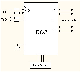
Figure 2: Universal Communication Controller
for Measurement Bus interfaced Sensors
(Source: pd Computer)
Distinction to other bus systems
The Measurement Bus was designed for the reliable and low-cost communication of equipment for the measurement, control and acquisition of process and operational data. Like many other field buses, it is less suited for the time-equidistant detection of highly dynamic processes ("scanning") with very short data records. This task can only be carried out in an optimum way by means of special sensor/actor bus systems. The Measurement Bus should also be distinguished from more costly high speed processor-processor networks, in which the random access of all users and the transmission of large amounts of data are required. But the transition to networks of this kind (eg MAP/MMS) can be achieved in a simple way using the master station as a gateway.
Realizations and User Support
In the European market Measurement Bus interfaces are be offered by more than 80 companies. A special application profil for petrol stations (EPSI) is standardized. More than 40 000 installed nodes in very different application areas and several countries are demonstrating the acceptance of the Measurement Bus concept.
The "Association of Measurement Bus Users" (ADM e.V.) gives advice to interested parties concerning the Measurement Bus's potential applications. It collates supplier lists, organises joint stands at fairs and provides technical information. A large number of publications show that there is a wide range of applications and that a number of applications have already been implemented. "Starter kits", development tools, test and simulation programs as well as the conformity testing office of the Chemnitz-Zwickau Technical University allow the user to graduate to working on his own developments without any problems. There is close cooperation with the DIN an CENELEC standards committee responsible. Further developments and research on the Measurement Bus are being carried out at the WZL of the RWTH Aachen, at the Chemnitz-Zwickau Technical University and at the University of Hannover.
Contact: Association of Measurement Bus Users (ADM e.V.), Appelstr. 9A, D-30167 Hannover, Germany
Tel: +44-511-762-4673 , Fax: +44-511-762-3917
email : wagner@geml.uni-hannover.de
9.3.98